GW9 Series 1000A Outdoor Disconnector Switch Ceramic Made Group Operated Disconnect Switches For Destribution Equipment
Product Decription:
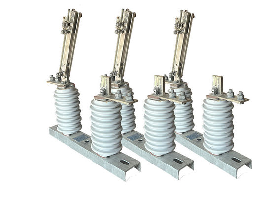
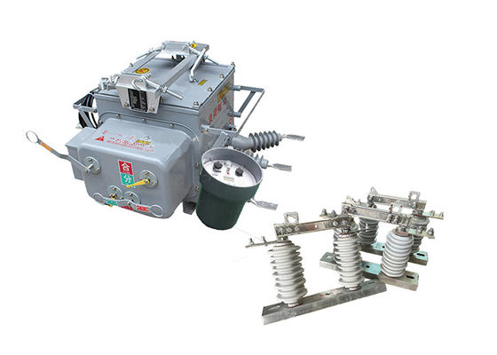
Outdoor disconnector switch is a type of portable device used for isolating and grounding electrical distribution lines for maintenance, repair, or emergency purposes. It is a versatile tool that can be used in a variety of applications, including overhead distribution lines, substations, and industrial facilities.
The outdoor disconnector switch is designed to be operated by a single person, making it easy to use and maneuver. It consists of a telescoping fiberglass pole, which can be extended to reach the electrical equipment, and a set of interchangeable attachments, which allow the user to perform a variety of tasks, such as opening or closing switches and grounding lines.
The outdoor disconnector switch is designed to provide a visible break in the electrical circuit, which helps protect against accidental contact with energized equipment. It is also designed to withstand harsh environmental conditions, such as high winds, rain, and snow, making it suitable for use in outdoor environments.
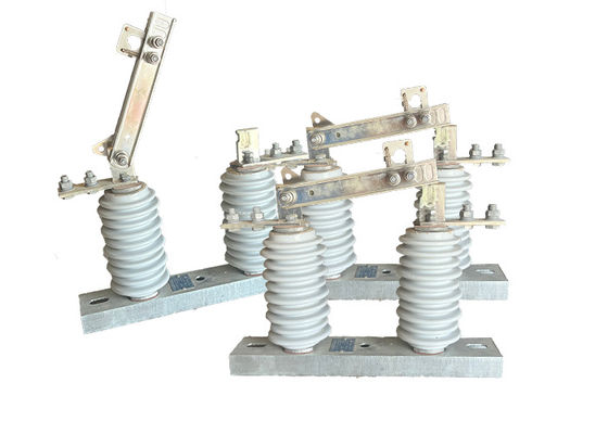
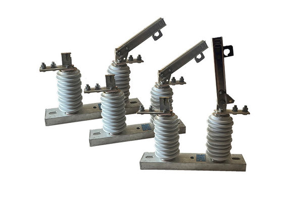
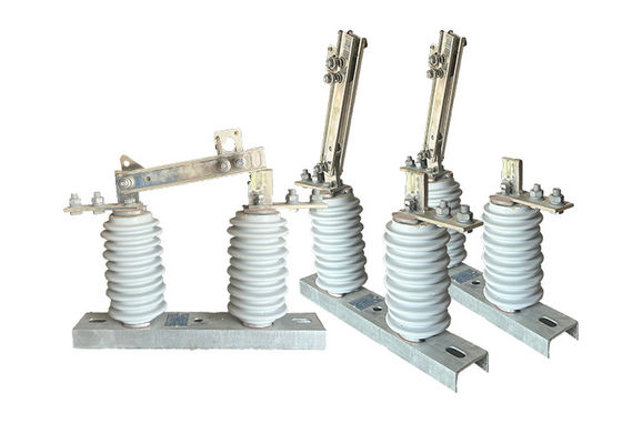
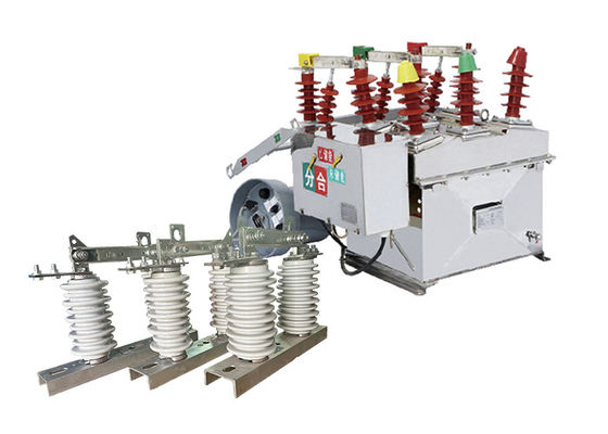
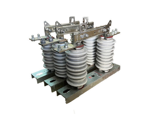
Structure:
This product is composed of base (plate), post insulator, conductive part and interlock device. One end of the knife is installed on the dynamic contact knife head through bolts, and the other end of the knife is separately connected with the static contact head, and each side is maintained in a good contact state by the pressure of the compression spring. Each knife is slot-shaped type, which not only increases the heat dissipation surface of the knife, but also conducive to reducing the temperature rise, and improve the mechanical strength of the knife, making the dynamic thermal stability against short circuit. The interlocking parts installed at the non-rotating end of the contact knife and the static locking hook on the static contact constitute the opening locking device, which is self-locking when the brake is closed, so that the brake knife will not fall off by itself due to its own weight or the action of electric power, resulting in the opening of the brake without cause.
Operation:
1.Closing the Switch: When the switch is closed, the two conductive parts of the circuit are brought into contact with each other, allowing electrical current to flow through the circuit.
2.Opening the Switch: When the switch is opened, an air gap is created between the two conductive parts of the circuit, effectively isolating the section from the rest of the system. This is typically done to allow maintenance, repair, or testing work to be carried out safely.
3.Grounding the Circuit: Before any work can be carried out on the isolated section of the circuit, it is important to ground the circuit to prevent any residual electrical charge from building up. This is typically done using an earth switch or grounding electrode.
Application:
1.Maintenance and Repair: The Loadbuster Electrical Isolator is commonly used to isolate and ground electrical distribution lines for maintenance and repair activities. It allows maintenance personnel to work safely on energized equipment without the risk of electrocution.
2.Emergency Response: The Loadbuster Electrical Isolator can be used in emergency situations, such as power outages or natural disasters, to isolate and ground electrical distribution lines and restore power safely.
3.Switching Operations: The Loadbuster Electrical Isolator can be used to open or close switches and perform other switching operations on electrical distribution lines.
Technical Parameters:
| Serial No. |
Parameter |
Unit |
Data |
| 1 |
Rated Voltage |
kV |
12 |
| 2 |
Rated Current |
Model No. |
(H)GW9-12(W)/630-20 |
A |
630 |
| (H)GW9-12(W)/1000-20 |
1000 |
| (H)GW9-12(W)/1250-31.5 |
1250 |
| 3 |
4s Short-time withstanding current |
Model No. |
(H)GW9-12(W)/630-20 |
kA |
50 |
| (H)GW9-12(W)/1000-20 |
50 |
| (H)GW9-12(W)/1250-31.5 |
80 |
| 4 |
Rated Insulation Level |
Lightning surge withstand voltage(peak) |
Polar-to-Earth
(Positive & Negative) |
kV |
75 |
Interfracture
(Positive & Negative) |
85 |
Industrial frequency withstand voltage
(1 min)
(Effective value) |
Dry Test/Wet Test |
Polar-to-Earth |
42(Dry)
34(Wet) |
| Interfracture |
48(Dry) |
| 48(Dry) |
48(Dry)
40(Wet) |
| 5 |
Main Circuit Resistance |
μ Ω |
630 |
| 1000 |
| 1250 |
| 6 |
Mechanical Life Time |
times |
50 |
| 50 |
80
|


 Your message must be between 20-3,000 characters!