Pole Mounted Circuit Breaker Fixed Installation Automatic Reset Mode Operated With High Voltage Disconnect Switch
Product Description:
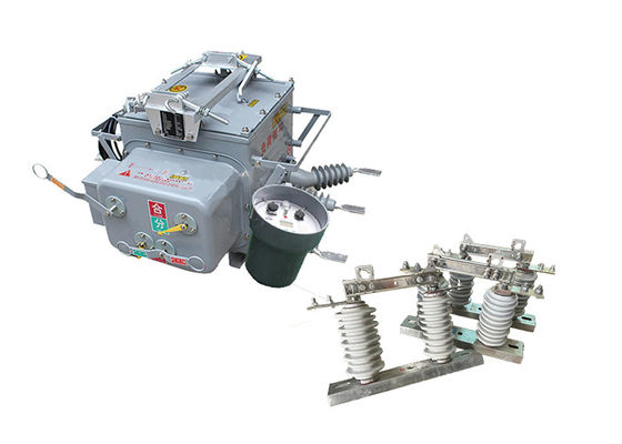
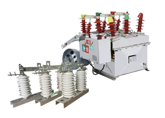
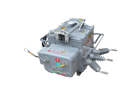
The ZW32-12(F) Pole Mounted Circuit Breaker is specifically designed for outdoor environments. It features enhanced durability and weather resistance, allowing it to withstand various harsh weather conditions such as rain, humidity, and extreme temperatures. This ensures reliable operation and longevity in outdoor installations.
It is capable of effectively breaking and closing load currents, overload currents, and short circuit currents in electronic systems. It provides reliable interruption and switching operations, ensuring the safety and proper functioning of the electrical system.
In addition to substations, the ZW32-12(F) Pole Mounted Circuit Breaker finds extensive application in industrial and mining enterprises. It offers reliable protection and control in the distribution systems of these facilities, safeguarding motors, transformers, and other electrical equipment from overcurrents and short circuits. This contributes to maintaining a stable and secure power supply in industrial and mining operations.
It is specifically designed to handle frequent operations in rural power grids. It serves as a sectional switch, allowing for efficient segmentation of the power grid. When equipped with a controller, it enables distribution network automation, improving the reliability and efficiency of the rural power system.
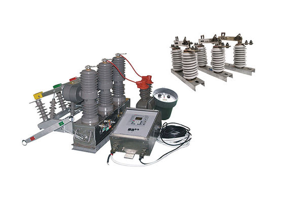
With the installation of a controller, the ZW32-12(F) Pole Mounted Circuit Breaker can seamlessly integrate into power grid operations. It enables remote monitoring, control, and automation of the distribution network, optimizing system performance and facilitating efficient energy management.
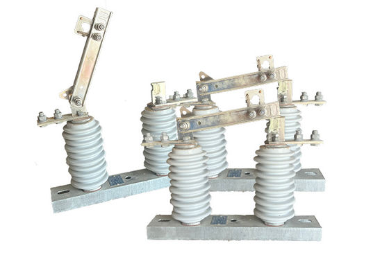
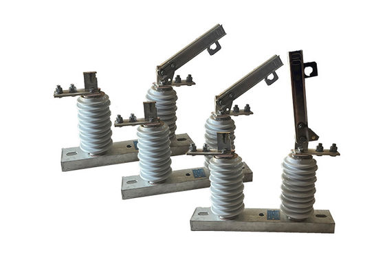
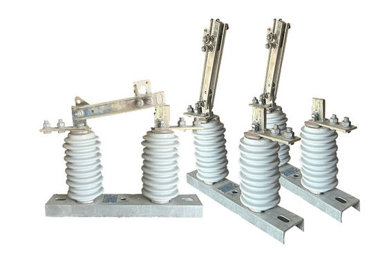
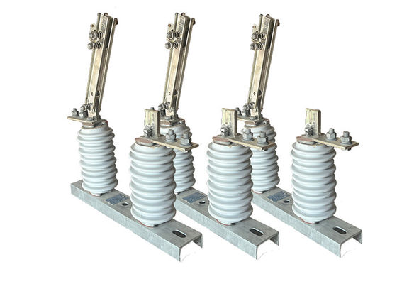
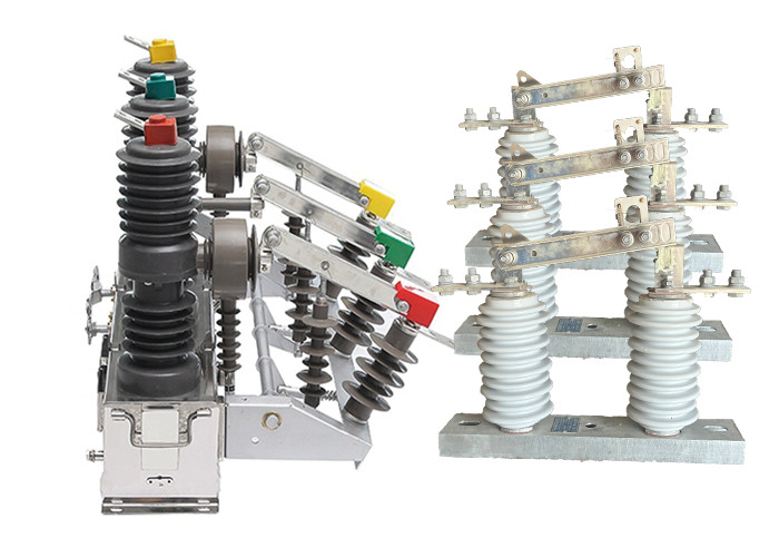
The GW9-10 High voltage disconnect switches are essential components in power transmission and distribution systems, as they allow for the isolation of specific sections of the network for maintenance or repair work. They can also be used to isolate sections of the network in the event of a fault or other abnormal condition.
These switches are designed to handle high voltages and currents, and are typically constructed from durable and robust materials such as stainless steel, aluminum or copper. They are designed to withstand harsh environmental conditions, such as extreme temperatures, high winds, and heavy rainfall.
There are several types of high voltage disconnect switches, including air-break switches, oil-immersed switches, and gas-insulated switches. Air-break switches are the most common type, and they wor k by using a set of contacts that physically separate when the switch is opened. Oil-immersed switches are typically used in high voltage applications and are filled with oil to prevent arcing when the switch is opened. Gas-insulated switches use sulfur hexafluoride gas to insulate the switch contacts, which allows for smaller and more compact switch designs.
High voltage disconnect switches must be operated and maintained by qualified personnel who have received proper training. Safety procedures must be followed when working with these switches, including the use of appropriate personal protective equipment and following lockout/tagout procedures to prevent accidental energization of the equipment. Regular maintenance and testing of high voltage disconnect switches is also important to ensure that they are functioning properly and are safe to use.
Double effect of using when GW9-10 series isolator swich can be used with the vacuum circuit breakers.
Controller Introduction:
1.With 485 / 232 communication interface, or through optical fiber, wireless remote monitoring; Acceleration function after reclosing;when the switch is heavy,automatic acceleration tripping in case of permanent fault;
2.Remote / manual closing to accelerate tripping, and closing reclosing: The user sends power after repairing the line, if he forgets to remove the grounding switch,should accelerate tripping.
3.Three reclosing delay time can be adjusted;
4.The jump closing circuit adopts anti-misoperation design and has anti-jump function;
5.Zero-sequence current can distinguish between in-zone and out-of-zone faults;
6.The remote control switch is designed to prevent misoperation.
Collocation:
The relation between the outdoor vacuum circuit breaker and the outdoor high-voltage disconnect isolator lies in their complementary roles in the electrical system:
Circuit Interruption: The vacuum circuit breaker is responsible for interrupting the electrical circuit during normal operation or in the event of a fault. It acts as the primary means of breaking the current flow. In contrast, the disconnect isolator is used for isolating the circuit from the power source during maintenance or repair activities. It provides an additional layer of safety by physically opening the circuit.
Coordination: In high-voltage power systems, the vacuum circuit breaker and the disconnect isolator are often coordinated to work together. The circuit breaker is responsible for detecting faults and tripping to interrupt the current flow, while the disconnect isolator is used to physically isolate the circuit and provide a visible indication of the disconnection.
Safety and Maintenance: The disconnect isolator plays a crucial role in ensuring the safety of maintenance personnel. Before any maintenance work can be performed on the electrical equipment, the disconnect isolator is operated to open the circuit and provide a visible air gap. This ensures that the equipment is de-energized and safe to work on. The vacuum circuit breaker, on the other hand, protects the system during normal operation and in the event of faults.
Introduction of GW9 series outdoor disconnector switch►
https://www.maoyt.com/test/hvdisconnectorswitch.com/sale-40466882-electrical-high-voltage-isolator-switch-gw9-series-630a-gray-color-overhead-line-group-diconnect-swi.html
Feature:
1.Three-phase pillar-type fully enclosed structure with high sealing performance.
A.Stable and reliable breaking performance, no combustion or explosion hazards; maintenance-free, small size, lightweight, and long service life.
B.Strong moisture and dew prevention performance, especially suitable for use in cold or humid areas.
C.Imported materials with good insulation performance, high temperature resistance, UV resistance, and aging resistance.
2.Efficient and reliable miniaturized spring operating mechanism.
A.The energy storage motor has low power consumption for opening and closing operations; the mechanism adopts a direct transmission method with fewer components, resulting in high reliability.
B.The operating mechanism is placed in a sealed box to effectively prevent rust and improve the reliability of the mechanism.
3.Convenient and flexible control and free combination performance.
A.It can be manually operated for breaking or electrically operated for opening and closing, as well as remotely controlled from a remote location.
B.It can be paired with an intelligent controller to achieve distribution automation or combined with a recloser controller to form an automatic recloser or sectionalizer.
C.It can be equipped with two-phase or three-phase current transformers for overcurrent or short circuit protection.
D.It can provide current acquisition signals for intelligent controllers and can be equipped with metering current transformers according to user requirements.
E.It can be equipped with a three-phase interlocking isolation switch with a built-in anti-misoperation interlocking device; it can also be installed with surge arrester pillar insulators for easy maintenance.
Structure:
The load switch is composed of three parts: pillar, base, and suspension for installation, fixing, and lifting.
1.The pillar-mounted high-voltage load switch with a vacuum arc extinguishing chamber has stable and reliable breaking performance. It features no combustion or explosion hazards, safety, maintenance-free, small size, lightweight, and long service life.
2.The load switch adopts a fully enclosed structure with good sealing performance, moisture and dew prevention capabilities, suitable for use in high-temperature and humid areas.
3.The load switch can be manually or electrically operated for opening and closing, and it can also be remote-controlled.
4.The operating mechanism is innovative, simple, reliable in action, compact in size, and has a mechanical life of up to 10,000 operations. The energy storage motor is a DC permanent magnet motor, and the voltage level can be selected from -220V, 110V, 48V, or 24V.
Application:
1.Substations: It is commonly used in both indoor and outdoor substations for protection and control of medium-voltage power distribution. The vacuum circuit breaker ensures reliable interruption of fault currents, overload currents, and load currents, safeguarding the substation equipment.
2.Industrial and mining enterprises: The ZW32-12 vacuum circuit breaker is employed in the distribution systems of industrial and mining enterprises to protect motors, transformers, and other electrical equipment from overcurrents and short circuits. It helps maintain the stability and safety of the power supply in these facilities.
3.Rural power grids: Due to its ability to withstand frequent operations, the vacuum circuit breaker is suitable for application in rural power grids. It can be used as a sectional switch, allowing for efficient segmentation of the power grid. Additionally, when equipped with a controller, it enables automation of the distribution network, improving the reliability and efficiency of the rural power system.
4.Commercial buildings: The vacuum circuit breaker is also utilized in commercial buildings for power distribution and protection. It ensures safe and reliable operation of electrical systems, preventing damage to equipment and minimizing downtime.
5.Railway systems: The ZW32-12 vacuum circuit breaker is also utilized in railway systems for protection and control of electrical installations, including signaling systems, traction power supply, and substations. It ensures safe and reliable operation of the railway infrastructure, contributing to the overall efficiency and performance of the system.
6.Oil and gas industry: The vacuum circuit breaker is employed in the oil and gas industry for protection of electrical equipment in refineries, pipelines, and offshore platforms. It ensures safe operation in hazardous environments and protects against potential electrical faults.
Technical Parameter:
ZW32-12
| Serial No. |
Parameter |
Unit |
Data |
| 1 |
Rated voltage |
kV |
12 |
| 2 |
Insulation level of Fracture |
Working Frequency(Dry Test/Wet Test) |
48 |
| Voltage of Lightning Shock Test (Peak) |
85 |
| 3 |
Level of Insulation to ground/phase to phase |
Working Frequency |
Dry Test |
42 |
| Wet Test |
34 |
| Voltage of Lightning Shock Test (Peak) |
75 |
| 4 |
Rated Current |
A |
630 |
| 5 |
Rated thermal stability current (Effective value) |
kA |
20 |
| 6 |
Rated short-circuit breaking current (Effective value) |
25 |
| 7 |
Rated thermal stability time |
s |
4 |
| 8 |
Rated short-circuit closing current(Peak) |
kA |
63 |
| 9 |
Rated dynamic stability current (Peak) |
| 10 |
Mechanical lifetime |
times |
10000 |
| 11 |
Opening rated current |
1000 |
| 12 |
Surrounding air temperature |
Highest Temperature |
℃ |
-55 |
| Lowest Temperature |
+60 |
| Difference ofMaximum daily temperature |
K |
≤25 |
| 13 |
Altitude |
m |
≤2500 |
| 14 |
Humidity |
Average of daily relative humidity |
% |
≤95 |
| Average of monthly relative humidity |
≤90 |
| 15 |
Earthquake-resistant capacity |
Horizontal acceleration |
g |
0.25 |
| Ground vertical acceleration |
0.125 |
| Safety Factor |
/ |
1.67 |
| 16 |
Wind Speed |
m/s |
≤35 |
| 17 |
Ice Thickness |
mm |
≤20 |
GW9-10
| Serial No. |
Parameter |
Unit |
Data |
| 1 |
Rated Voltage |
kV |
12 |
| 2 |
Rated Current |
Model No. |
(H)GW9-12(W)/630-20 |
A |
630 |
| (H)GW9-12(W)/1000-20 |
1000 |
| (H)GW9-12(W)/1250-31.5 |
1250 |
| 3 |
4s Short-time withstanding current |
Model No. |
(H)GW9-12(W)/630-20 |
kA |
50 |
| (H)GW9-12(W)/1000-20 |
50 |
| (H)GW9-12(W)/1250-31.5 |
80 |
| 4 |
Rated Insulation Level |
Lightning surge withstand voltage(peak) |
Polar-to-Earth
(Positive & Negative) |
kV |
75 |
Interfracture
(Positive & Negative) |
85 |
Industrial frequency withstand voltage
(1 min)
(Effective value) |
Dry Test/Wet Test |
Polar-to-Earth |
42(Dry)
34(Wet) |
| Interfracture |
48(Dry) |
| 48(Dry) |
48(Dry)
40(Wet) |
| 5 |
Main Circuit Resistance |
μ Ω |
630 |
| 1000 |
| 1250 |
| 6 |
Mechanical Life Time |
times |
50 |
| 50 |
| 80 |


 Your message must be between 20-3,000 characters!