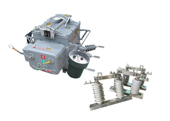
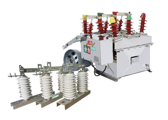
ZW32-12 Series Pole Mounted Automatic Circuit Breaker Easy Operation GB1984 / GB11022 With Outdoor Disconnect Switch
Product Description:
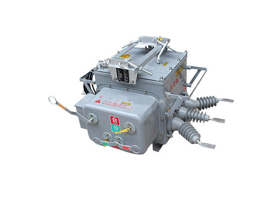
ZW32-12 pole mounted circuit breaker is a fixed voltage 12KV, three-phase AC 50Hz outdoor distribution equipment. It is mainly used for breaking and closing load current, overload current and short circuit current. The utility model is suitable for the protection and control in the distribution system of substations and industrial and mining enterprises, and the places where the rural power grid operates frequently. It can also operate the segmented switch of the power grid, and after installing the controller, it can realize the automation of the distribution network.
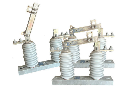
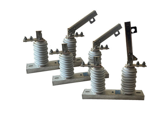
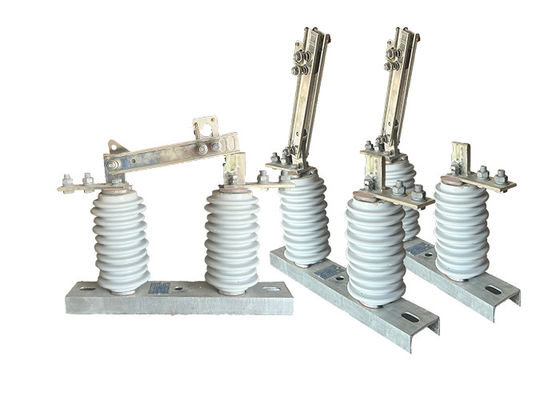
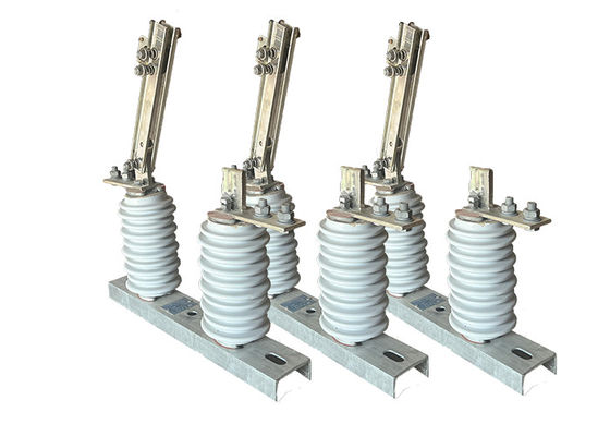
GW9-10 high voltage disconnect switch is an electrical switch that is designed to isolate a section of an electrical network or system from the rest of the system for maintenance or repair purposes. It is typically used in high voltage power transmission and distribution systems.
The switch is designed to open and close under normal or abnormal conditions, such as a fault or overcurrent. When the switch is open, it physically disconnects the section of the system from the rest of the network, preventing the flow of electricity to that section.
High voltage disconnect switches are typically designed to operate at voltages between 600 volts and 765,000 volts, and they can be operated manually or automatically. They are typically installed in substations or on power poles, and they are an important component of the electrical grid infrastructure.
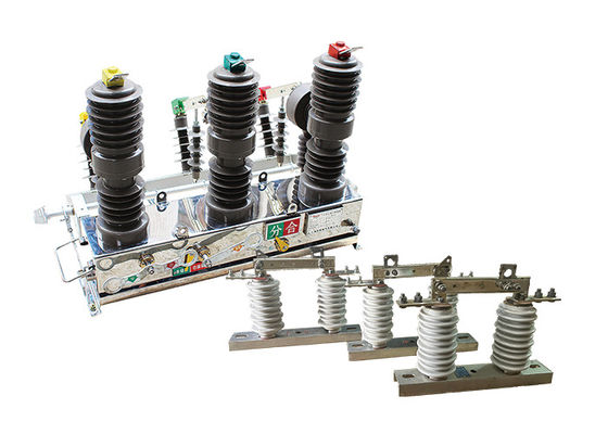
double effect of using when the circuit breakers used with isolation disconnector!!
Structure:
1.Frame: The frame serves as the main structural component of the circuit breaker, providing support and housing for the internal components.
2.Current Carrying Components: These components include the contacts, conductors, and current-carrying parts that form the electrical path through the circuit breaker. They are responsible for conducting and interrupting the flow of current.
3.Permanent Magnet Assembly: The permanent magnet assembly is a crucial component of the circuit breaker. It consists of permanent magnets that generate a magnetic field to control the tripping action of the circuit breaker. The magnets are carefully positioned to provide the desired magnetic force for efficient and precise operation.
4.Tripping Mechanism: The tripping mechanism is responsible for initiating the opening of the circuit breaker when a fault or overload condition is detected. In an Intelligent Permanent Magnetic Circuit Breaker, the tripping mechanism is designed to respond rapidly and accurately to the fault signals received from the intelligent control system.
5.Intelligent Control System: The intelligent control system is the brain of the circuit breaker. It typically includes microprocessors, sensors, and other electronic components that monitor electrical parameters, analyze fault conditions, and control the operation of the circuit breaker. The control system may also feature communication interfaces for remote monitoring, data logging, and integration with other systems.
6.Auxiliary Components: Various auxiliary components may be present in an Intelligent Permanent Magnetic Circuit Breaker, depending on the specific application and requirements. These can include indicators, auxiliary contacts for signaling and control purposes, mechanical interlocks, and terminals for external wiring connections.
7.Enclosure: The circuit breaker is typically enclosed within a housing to provide protection against environmental factors, such as dust, moisture, and physical damage. The enclosure may be made of durable materials like metal or high-quality plastics.
Feature:
1.Three-phase pillar-type fully enclosed structure with high sealing performance.
A.Stable and reliable breaking performance, no combustion or explosion hazards; maintenance-free, small size, lightweight, and long service life.
B.Strong moisture and dew prevention performance, especially suitable for use in cold or humid areas.
C.Imported materials with good insulation performance, high temperature resistance, UV resistance, and aging resistance.
2.Efficient and reliable miniaturized spring operating mechanism.
A.The energy storage motor has low power consumption for opening and closing operations; the mechanism adopts a direct transmission method with fewer components, resulting in high reliability.
B.The operating mechanism is placed in a sealed box to effectively prevent rust and improve the reliability of the mechanism.
3.Convenient and flexible control and free combination performance.
A.It can be manually operated for breaking or electrically operated for opening and closing, as well as remotely controlled from a remote location.
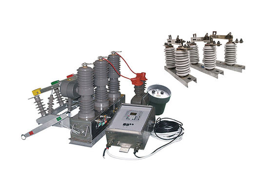
B.It can be paired with an intelligent controller to achieve distribution automation or combined with a recloser controller to form an automatic recloser or sectionalizer.
C.It can be equipped with two-phase or three-phase current transformers for overcurrent or short circuit protection.
D.It can provide current acquisition signals for intelligent controllers and can be equipped with metering current transformers according to user requirements.
E.It can be equipped with a three-phase interlocking isolation switch with a built-in anti-misoperation interlocking device; it can also be installed with surge arrester pillar insulators for easy maintenance.
Application:
1.Substations: It is commonly used in both indoor and outdoor substations for protection and control of medium-voltage power distribution. The vacuum circuit breaker ensures reliable interruption of fault currents, overload currents, and load currents, safeguarding the substation equipment.
2.Industrial and mining enterprises: The ZW32-12 vacuum circuit breaker is employed in the distribution systems of industrial and mining enterprises to protect motors, transformers, and other electrical equipment from overcurrents and short circuits. It helps maintain the stability and safety of the power supply in these facilities.
3.Rural power grids: Due to its ability to withstand frequent operations, the vacuum circuit breaker is suitable for application in rural power grids. It can be used as a sectional switch, allowing for efficient segmentation of the power grid. Additionally, when equipped with a controller, it enables automation of the distribution network, improving the reliability and efficiency of the rural power system.
4.Commercial buildings: The vacuum circuit breaker is also utilized in commercial buildings for power distribution and protection. It ensures safe and reliable operation of electrical systems, preventing damage to equipment and minimizing downtime.
Technical Parameter:
ZW32-12
| Serial No. |
Parameter |
Unit |
Data |
| 1 |
Rated voltage |
kV |
12 |
| 2 |
Insulation level of Fracture |
Working Frequency(Dry Test/Wet Test) |
48 |
| Voltage of Lightning Shock Test (Peak) |
85 |
| 3 |
Level of Insulation to ground/phase to phase |
Working Frequency |
Dry Test |
42 |
| Wet Test |
34 |
| Voltage of Lightning Shock Test (Peak) |
75 |
| 4 |
Rated Current |
A |
630 |
| 5 |
Rated thermal stability current (Effective value) |
kA |
20 |
| 6 |
Rated short-circuit breaking current (Effective value) |
25 |
| 7 |
Rated thermal stability time |
s |
4 |
| 8 |
Rated short-circuit closing current(Peak) |
kA |
63 |
| 9 |
Rated dynamic stability current (Peak) |
| 10 |
Mechanical lifetime |
times |
10000 |
| 11 |
Opening rated current |
1000 |
| 12 |
Surrounding air temperature |
Highest Temperature |
℃ |
-55 |
| Lowest Temperature |
+60 |
| Difference ofMaximum daily temperature |
K |
≤25 |
| 13 |
Altitude |
m |
≤2500 |
| 14 |
Humidity |
Average of daily relative humidity |
% |
≤95 |
| Average of monthly relative humidity |
≤90 |
| 15 |
Earthquake-resistant capacity |
Horizontal acceleration |
g |
0.25 |
| Ground vertical acceleration |
0.125 |
| Safety Factor |
/ |
1.67 |
| 16 |
Wind Speed |
m/s |
≤35 |
| 17 |
Ice Thickness |
mm |
≤20 |
GW9-10
| Serial No. |
Parameter |
Unit |
Data |
| 1 |
Rated Voltage |
kV |
12 |
| 2 |
Rated Current |
Model No. |
(H)GW9-12(W)/630-20 |
A |
630 |
| (H)GW9-12(W)/1000-20 |
1000 |
| (H)GW9-12(W)/1250-31.5 |
1250 |
| 3 |
4s Short-time withstanding current |
Model No. |
(H)GW9-12(W)/630-20 |
kA |
50 |
| (H)GW9-12(W)/1000-20 |
50 |
| (H)GW9-12(W)/1250-31.5 |
80 |
| 4 |
Rated Insulation Level |
Lightning surge withstand voltage(peak) |
Polar-to-Earth
(Positive & Negative) |
kV |
75 |
Interfracture
(Positive & Negative) |
85 |
Industrial frequency withstand voltage
(1 min)
(Effective value) |
Dry Test/Wet Test |
Polar-to-Earth |
42(Dry)
34(Wet) |
| Interfracture |
48(Dry) |
| 48(Dry) |
48(Dry)
40(Wet) |
| 5 |
Main Circuit Resistance |
μ Ω |
630 |
| 1000 |
| 1250 |
| 6 |
Mechanical Life Time |
times |
50 |
| 50 |
| 80 |


 Your message must be between 20-3,000 characters!