Outdoor Distribution HV Pole Mounted Circuit Breaker With Controller Of Smart System Matching With Outdoor Hookstick
Product Description:
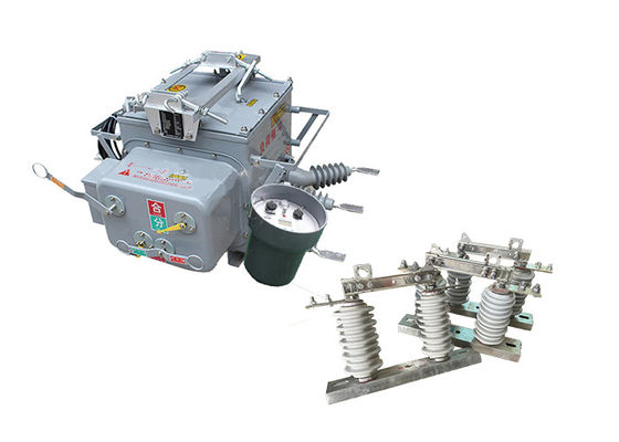
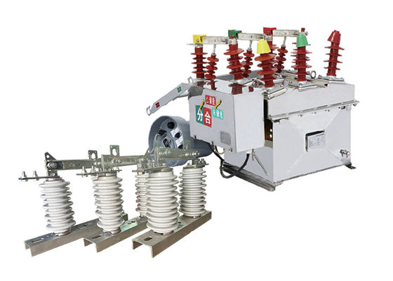
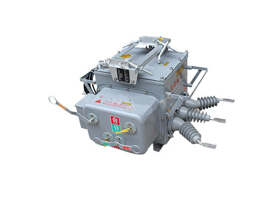
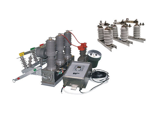
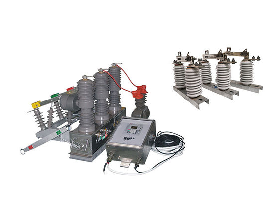
ZW32-12(F) high voltage pole mounted circuit breaker is an outdoor distribution equipment with a rated voltage of 12kV and a three-phase AC frequency of 50Hz. It is mainly used for breaking and closing the load current, overload current, and short circuit current in electronic systems. It is suitable for protection and control in substations and industrial and mining enterprise distribution systems, as well as for frequent operations in rural power grids. It can also be used as a sectional switch for power grid operation. With the installation of a controller, the ZW32-12 automatic recloser electrical sectionlizer can seamlessly integrate into power grid operations. It enables remote monitoring, control, and automation of the distribution network, optimizing system performance and facilitating efficient energy management.
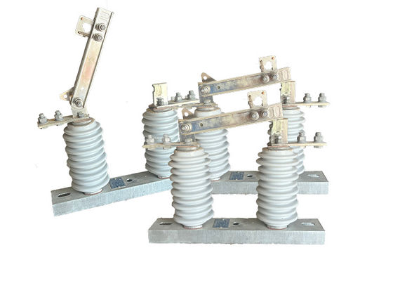
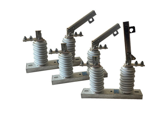
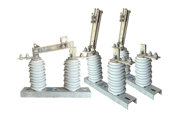
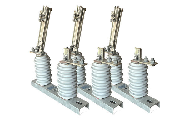
The GW9-10 operated hookstick is a type of electrical switch used to isolate a section of an overhead power transmission line for maintenance or repair. It is typically used in high voltage electrical systems, such as those used by power utilities to transmit electricity over long distances.
The hookstick is mounted on an overhead structure, such as a transmission tower or pole, and is designed to withstand the harsh environmental conditions encountered in outdoor electrical systems. It features a vertical, or up-and-down, motion to engage or disengage the switch contacts, which are typically made of copper or other conductive materials.
The hookstick is designed to provide a visible break in the transmission line, allowing maintenance personnel to safely work on the line without risk of electrocution or damage to equipment. It is often used in conjunction with other safety devices, such as grounding switches and surge arrestors, to protect the electrical system and the people working on it.
Controller Introduction:
The controller supports communication via a 485/232 interface, which allows for remote monitoring and control. It can also communicate through optical fiber or wireless connections.
When a heavy switch is detected, the device automatically accelerates the tripping process in the event of a permanent fault. This feature helps protect the system from damage in such situations.
Remote/Manual Closing and Reclosing: The user has the option to remotely or manually close and reclose the circuit. Additionally, if the user forgets to remove the grounding switch when restoring power after repairing a line, the device can accelerate the tripping process to ensure safety.
It allows for the adjustment of three reclosing delay times. This feature provides flexibility in determining the appropriate delay before reclosing the circuit after a fault.
The jump closing circuit of the controller incorporates an anti-misoperation design. It includes an anti-jump function to prevent unintended closure of the circuit.
The controller can distinguish between in-zone and out-of-zone faults based on zero-sequence current. This capability helps identify the location of faults and enables more targeted troubleshooting and maintenance.
Prevention of Misoperation: The remote control switch is designed to prevent misoperations. This design feature ensures that the switch is not accidentally triggered, thereby reducing the risk of unintended actions.
Application:
1.Power Distribution Systems: The circuit breaker can be used in power distribution networks, including substations, switchgear, and distribution panels. Its intelligent control features provide enhanced monitoring and protection capabilities, allowing for efficient and reliable operation of the distribution system.
2.Industrial Installations: The circuit breaker is suitable for protecting electrical equipment and machinery in industrial settings. It can be employed in motor control centers, control panels, and process automation systems, ensuring the safety and uninterrupted operation of critical industrial processes.
3.Renewable Energy Systems: The circuit breaker is well-suited for use in renewable energy systems, such as solar power plants and wind farms. It offers precise fault detection and rapid tripping, ensuring the protection of sensitive renewable energy equipment and preventing damage caused by overloads or faults.
4.Data Centers: Data centers require highly reliable and responsive circuit protection to safeguard critical IT infrastructure. The Intelligent Permanent Magnetic Circuit Breaker can be utilized in data center power distribution units (PDUs) and electrical panels, offering advanced monitoring, quick fault detection, and optimized energy management.
5.Electric Vehicle Charging Stations: With the increasing adoption of electric vehicles (EVs), the Intelligent Permanent Magnetic Circuit Breaker can be used in EV charging stations. It provides fast and accurate protection against overcurrents and short circuits, ensuring safe and reliable charging operations.
6.Energy Management Systems: The intelligent control features of the circuit breaker make it compatible with energy management systems. It can be integrated into smart home or building automation systems to optimize energy consumption, monitor electrical parameters, and enable load shedding or demand response functions.
Feature:
1.High-voltage vacuum circuit breaker: It adopts vacuum arc extinguishing technology and has good breaking performance and strong arc extinguishing capability. It can reliably interrupt load currents, overload currents, and short circuit currents.
2.Outdoor design: It is suitable for outdoor environments and has good weather resistance and protection performance, allowing it to operate normally under various harsh weather conditions.
3.Rated voltage and frequency: It is suitable for distribution systems with a rated voltage of 12kV and a three-phase AC frequency of 50Hz, meeting the corresponding power requirements.
4.Protection and control functionality: It is mainly used for load protection and control in substations and industrial and mining enterprise distribution systems. It can effectively protect the safe operation of power equipment and systems.
5.Rural power grid application: Due to the frequent operations in rural power grids, this circuit breaker is widely used and can be used as a sectional switch and for distribution network automation in rural power grids.
Condition:
1.Altitude of not more than 2000 meters;
2.Ambient air temperature: -45 ° C ~ + 40 ° C. Daily temperature difference: 25 ° C;
3.Wind speed not more than 35 m / s
4.No flammable, explosive dangerous chemical corrosion and violent vibration places.
Technical Parameter:
ZW32-12
| Serial No. |
Parameter |
Unit |
Data |
| 1 |
Rated voltage |
kV |
12 |
| 2 |
Insulation level of Fracture |
Working Frequency(Dry Test/Wet Test) |
48 |
| Voltage of Lightning Shock Test (Peak) |
85 |
| 3 |
Level of Insulation to ground/phase to phase |
Working Frequency |
Dry Test |
42 |
| Wet Test |
34 |
| Voltage of Lightning Shock Test (Peak) |
75 |
| 4 |
Rated Current |
A |
630 |
| 5 |
Rated thermal stability current (Effective value) |
kA |
20 |
| 6 |
Rated short-circuit breaking current (Effective value) |
25 |
| 7 |
Rated thermal stability time |
s |
4 |
| 8 |
Rated short-circuit closing current(Peak) |
kA |
63 |
| 9 |
Rated dynamic stability current (Peak) |
| 10 |
Mechanical lifetime |
times |
10000 |
| 11 |
Opening rated current |
1000 |
| 12 |
Surrounding air temperature |
Highest Temperature |
℃ |
-55 |
| Lowest Temperature |
+60 |
| Difference ofMaximum daily temperature |
K |
≤25 |
| 13 |
Altitude |
m |
≤2500 |
| 14 |
Humidity |
Average of daily relative humidity |
% |
≤95 |
| Average of monthly relative humidity |
≤90 |
| 15 |
Earthquake-resistant capacity |
Horizontal acceleration |
g |
0.25 |
| Ground vertical acceleration |
0.125 |
| Safety Factor |
/ |
1.67 |
| 16 |
Wind Speed |
m/s |
≤35 |
| 17 |
Ice Thickness |
mm |
≤20 |
GW9-10
| Serial No. |
Parameter |
Unit |
Data |
| 1 |
Rated Voltage |
kV |
12 |
| 2 |
Rated Current |
Model No. |
(H)GW9-12(W)/630-20 |
A |
630 |
| (H)GW9-12(W)/1000-20 |
1000 |
| (H)GW9-12(W)/1250-31.5 |
1250 |
| 3 |
4s Short-time withstanding current |
Model No. |
(H)GW9-12(W)/630-20 |
kA |
50 |
| (H)GW9-12(W)/1000-20 |
50 |
| (H)GW9-12(W)/1250-31.5 |
80 |
| 4 |
Rated Insulation Level |
Lightning surge withstand voltage(peak) |
Polar-to-Earth
(Positive & Negative) |
kV |
75 |
Interfracture
(Positive & Negative) |
85 |
Industrial frequency withstand voltage
(1 min)
(Effective value) |
Dry Test/Wet Test |
Polar-to-Earth |
42(Dry)
34(Wet) |
| Interfracture |
48(Dry) |
| 48(Dry) |
48(Dry)
40(Wet) |
| 5 |
Main Circuit Resistance |
μ Ω |
630 |
| 1000 |
| 1250 |
| 6 |
Mechanical Life Time |
times |
50 |
| 50 |
| 80 |


 Your message must be between 20-3,000 characters!