Three Phases Vcb Outdoor AC Automatic Vacuum Circuit Breaker Stainless Steel With Intelligent Controller
Product Description:
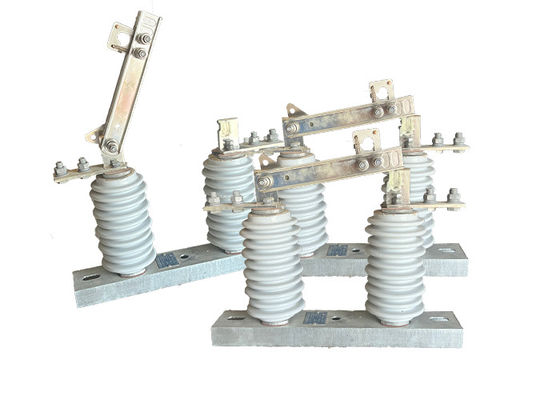
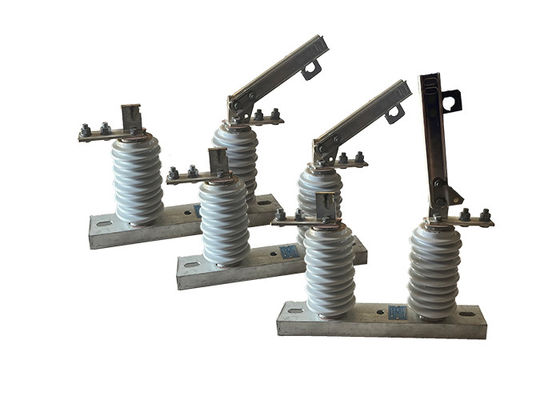
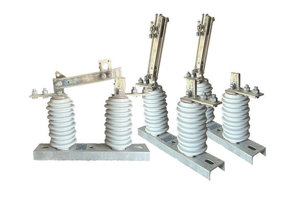
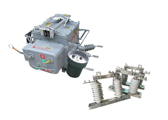
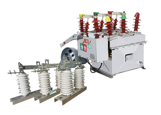
The ZW20-12(F) automatic vacuum circuit breaker is specifically designed for outdoor use in rural and urban 10 kV distribution networks. It is capable of handling various scenarios such as load current, overload current, and short circuit current.
The circuit breaker features a three-phase common box structure, which includes essential components like the operating mechanism, conductive circuit, insulating system, sealing element, and shell. These components work in harmony to ensure the efficient and safe operation of the circuit breaker.
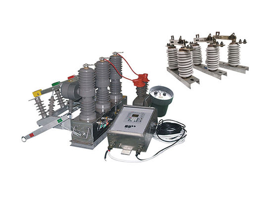
To further enhance control and monitoring capabilities, the ZW20-12(F) breaker is equipped with intelligent remote terminals. These terminals enable integration with distribution automation applications, allowing for remote control and real-time monitoring of the circuit breaker.
In addition to the ZW20-12(F) variant, there is another option available called the ZW20-12(Z). This variant is an outdoor intelligent high voltage AC true air breaker that incorporates a GSM short message function. This functionality enables communication via text messages, providing an additional means of control and communication for the breaker.
Furthermore, the ZW20-12(F) breaker can be combined with a dividing switch controller to create an outdoor dividing high voltage AC true air breaker system. This combination enhances the overall functionality and versatility of the circuit breaker, offering comprehensive control and protection capabilities.
Characteristics of the controller:
1. Can be equipped with 485 / 232 communication interface, or through optical fiber, wireless remote monitoring; reclosing acceleration function: when the switch is heavy
2. Automatic acceleration tripping in case of permanent failure
3. Remote control / manual closing accelerates tripping and locking reclosing: if the user overhauls the line and transmits electricity, if he forgets to remove the grounding knife brake, the trip should be accelerated
4. The delay time of three reclosing can be adjusted.
5. The tripping circuit adopts the design of anti-misoperation and has the function of preventing jumping.
6. Zero sequence current can fail in and out of the zone.
7. The remote control opening and closing adopts the design of preventing misoperation.
Feature:
1.The ZW20-12(F) automatic vacuum circuit breaker demonstrates a robust ability to withstand pollution. It is designed to resist the effects of environmental contaminants, ensuring reliable performance even in polluted conditions. It also exhibits high and low-temperature resistance, enabling operation in a wide range of temperature environments. Additionally, the circuit breaker poses no combustion or explosion hazards, enhancing overall safety.
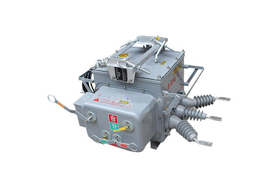
2.Featuring a fully enclosed structure, the circuit breaker is filled with SF6 gas within the enclosure. This design provides excellent sealing performance, making it suitable for deployment in high-temperature and humid areas. The sealed enclosure protects internal components from external elements, ensuring optimal performance and longevity.
3.The circuit breaker comes equipped with a current transformer (CT) that outputs current to the intelligent controller for information analysis. The transformation ratio of the CT is adjustable, allowing for flexibility in configuring the system. The connection terminals can be easily connected to the corresponding terminal sockets, facilitating convenient installation and maintenance processes.
4.The operating mechanism of the circuit breaker is innovative and simple, resulting in a compact size and lightweight construction. This design ensures safe and reliable operation, minimizing the risk of malfunction or failure. The compact size also contributes to space-saving installation and ease of handling.
5.The outer casing of the circuit breaker features conspicuous indicators for "energy storage," "open," and "close" states. These indicators provide clear visual cues, enabling easy identification of the operational status of the circuit breaker. This visual feedback enhances operational efficiency and ensures accurate monitoring of the circuit breaker's state.
Structure:
1.The microcomputer-based relay protection and monitoring device serves as the controller for the circuit breaker system. It utilizes advanced microcomputer technology to provide precise and efficient relay protection and monitoring functions.
2.The controller is designed with robust weather resistance, allowing it to withstand various environmental conditions. It is also equipped with protection against condensation, ensuring reliable operation even in humid or damp environments.
3.To establish a secure and dependable connection, the controller is linked to the switch body using aviation connectors. These connectors offer a high level of stability and durability, ensuring proper communication and functionality between the controller and the switch.
4.The controller boasts excellent connection reliability, minimizing the risk of signal loss or disruption. It maintains a high protection level, safeguarding the integrity and accuracy of the relay protection and monitoring system.
Environmental conditions:
1.Altitude:2000 meters
2.Ambient temperature:outdoors -30℃~+55℃
The highest annual average temperature is 20℃
Maximum daily average temperature is 30℃
3.Relative humidity:95%(25℃)
4.Seismic capacity:ground level acceleration 0.3g
Ground vertical acceleration 0.15g
While acting for three sine waves
Safety factor 1.67
5.Seismic intensity:7degrees
6. Maximum daily temperature difference:25℃
7.Installation location:outdoor, 10kv overhead line user responsibility demarcation point
8.Grounding method:Neutral point does not touch, the arc suppression coil grounding and low resistance grounding
Technical Parameters:
| Serial No. |
Parameter |
Unit |
Data |
| 1 |
Rated voltage |
kV |
12 |
| 2 |
Insulation level of Fracture |
Working Frequency(Dry Test/Wet Test) |
48 |
| Voltage of Lightning Shock Test (Peak) |
85 |
| 3 |
Level of Insulation to ground/phase to phase |
Working Frequency |
Dry Test |
42 |
| Wet Test |
34 |
| Voltage of Lightning Shock Test (Peak) |
75 |
| 4 |
Rated Current |
A |
630, 1250 |
| 5 |
Rated short-circuit breaking current |
kA |
16, 20, 25 |
| 6 |
Rated short-circuit breaking current breaking times |
times |
30 |
| 7 |
Rated short-time withstanding current |
kA |
16, 20, 25 |
| 8 |
Rated short-circuit duration |
S |
4 |
| 9 |
Rated short-circuit closing current (peak) |
kA |
40, 50, 63 |
| 10 |
Rated peak withstanding current |
kA |
40, 50, 63 |
| 11 |
Mechanical lifetime |
times |
over 1000 |
| 12 |
Opening rated current |
10000 |
| 13 |
Net Weight |
kg |
180 |
Technical Parameter of Controller:
| Serial No. |
Parameter |
Data |
| 1 |
Woking input voltage |
AC220V |
| 2 |
Input working frequency |
50Hz |
| 3 |
Allowable voltage fluctuation range for input voltage |
±20% |
| 4 |
Total power consumption of the device |
<10W |
| 5 |
Sampling value of phase current input |
60-600A |
| 6 |
Low voltage operation threshold |
10-140V |
| 7 |
Allowable sampling error for power input value |
±5% |
| 8 |
Overcurrent protection delay time value |
0.1-0.3s |
| 9 |
Setting value for zero-sequence current |
0.2-6A |
| 10 |
Grounding action delay time |
0-1200s |


 Your message must be between 20-3,000 characters!