630A Powerful Automatic Vacuum Circuit Breaker 180kg AC 50Hz Ndustrial Electrical Equipment Boundary Circuit Breaker
Product Description:
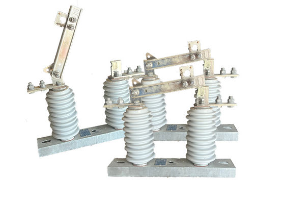
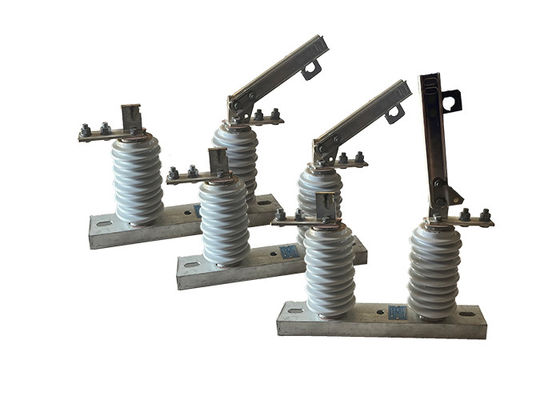
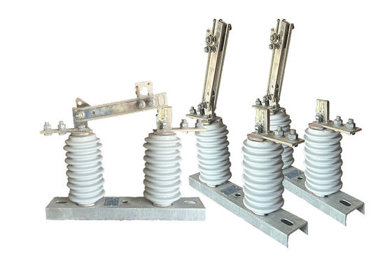
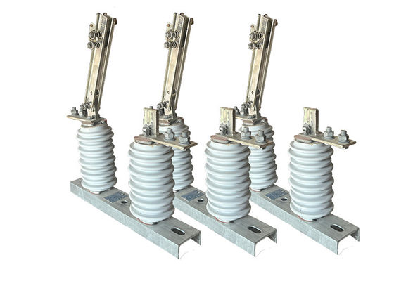
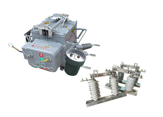
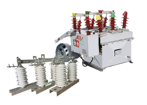
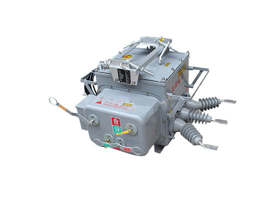
The ZW20-12(F) automatic vacuum circuit breaker is a type of three-phase AC 50Hz outdoor high voltage switchgear primarily designed for use in rural and urban 10 kV outdoor distribution networks. It serves to handle load current, overload current, short circuit current, and similar scenarios.
The circuit breaker features a three-phase common box structure, consisting of several components, including an operating mechanism, a conductive circuit, an insulating system, a sealing element, and a shell. These components work together to ensure the efficient and safe operation of the circuit breaker.
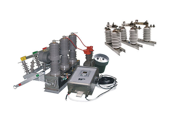
Additionally, the ZW20-12(F) breaker is equipped with intelligent remote terminals that support various distribution automation applications, allowing for enhanced control and monitoring capabilities.
Moreover, there is another variant of this circuit breaker called ZW20-12(Z), which is an outdoor intelligent high voltage AC true air breaker. It incorporates a GSM short message function, enabling communication via text messages.
Furthermore, the ZW20-12(F) breaker can be combined with a dividing switch controller to form an outdoor dividing high voltage AC true air breaker system. This combination enhances the functionality and versatility of the circuit breaker, providing more comprehensive control and protection capabilities.
Characteristics of the controller:
1.The circuit breaker system can be equipped with a 485/232 communication interface, allowing for convenient communication and data exchange with external devices. Alternatively, it can achieve long-distance monitoring by utilizing fiber optics or wireless communication technologies. These communication options enable efficient monitoring and control of the circuit breaker system from remote locations.
2.In the event of a permanent fault, the circuit breaker system automatically activates its acceleration to trip functionality. This feature ensures swift and effective tripping of the switch, helping to prevent further damage or hazards caused by the fault.
3.The circuit breaker system supports both remote control and manual reclosing with acceleration to trip capability. It also incorporates a reclosing interlock feature. If the user restores power to the line after repairing it but forgets to remove the grounding knife switch, the system will automatically accelerate to trip as a safety precaution.
4.The delay time for reclosing can be adjusted for all three attempts of reclosing. This flexibility allows for customization based on specific system requirements or operating conditions.
5.The trip/reclosing circuit of the circuit breaker system is designed to prevent false operations. This design ensures that the system accurately responds to genuine faults or abnormalities while minimizing the occurrence of unnecessary or incorrect tripping or reclosing actions. It also incorporates anti-reclosing functionality to enhance the overall safety and reliability of the system.
6.The system's ability to measure zero-sequence current enables it to differentiate between faults occurring within the protected zone and those originating from outside the zone. This differentiation helps in identifying the precise location of faults and enables appropriate actions to be taken for fault isolation and system protection.
7.The remote control trip/reclosing feature of the circuit breaker system is designed to prevent false operations. This designed to prevent false operations. This design ensures that remote commands for tripping or reclosing are executed accurately and reliably, reducing the risk of incorrect or unintended operations that could potentially compromise system safety or stability.
Feature:
1 Strong anti-fouling ability, high resistance to high and low temperature strength, no danger of combustion and explosion.
2 fully enclosed structure, the box filled with SF6 gas, good sealing, suitable for high temperature and humid areas.
3 built-in CT, output current for the intelligent control device for information analysis, and the ratio can be adjusted, the connection terminal connected to the corresponding terminal.
4 operating mechanism is novel, simple, small size, light weight, safe and reliable operation.
5 The shell prominently indicates the "energy storage," "points," and "combined" states.
Structure:
1.The microcomputer-based relay protection and monitoring device serves as the controller for the circuit breaker system. It utilizes advanced microcomputer technology to provide precise and efficient relay protection and monitoring functions.
2.The controller is designed with robust weather resistance, allowing it to withstand various environmental conditions. It is also equipped with protection against condensation, ensuring reliable operation even in humid or damp environments.
3.To establish a secure and dependable connection, the controller is linked to the switch body using aviation connectors. These connectors offer a high level of stability and durability, ensuring proper communication and functionality between the controller and the switch.
4.The controller boasts excellent connection reliability, minimizing the risk of signal loss or disruption. It maintains a high protection level, safeguarding the integrity and accuracy of the relay protection and monitoring system.
Environmental conditions:
1 ambient air temperature: -40 ° C ~ + 70 ° C;
2 Altitude: not more than 3000 m
3 Ambient air may be contaminated by dust, smoke, corrosive gases, steam or salt spray. Contamination Level: Class IV:
4 Wind speed does not exceed 34 m / s (equivalent to 700 Pa on the surface of the cylinder);
5 Vibration or ground motion from outside the switchgear and control equipment is negligible;
6 The amplitude of induced electromagnetic interference in the secondary system does not exceed 1.6kV.
Technical Parameters:
| Serial No. |
Parameter |
Unit |
Data |
| 1 |
Rated voltage |
kV |
12 |
| 2 |
Insulation level of Fracture |
Working Frequency(Dry Test/Wet Test) |
48 |
| Voltage of Lightning Shock Test (Peak) |
85 |
| 3 |
Level of Insulation to ground/phase to phase |
Working Frequency |
Dry Test |
42 |
| Wet Test |
34 |
| Voltage of Lightning Shock Test (Peak) |
75 |
| 4 |
Rated Current |
A |
630, 1250 |
| 5 |
Rated short-circuit breaking current |
kA |
16, 20, 25 |
| 6 |
Rated short-circuit breaking current breaking times |
times |
30 |
| 7 |
Rated short-time withstanding current |
kA |
16, 20, 25 |
| 8 |
Rated short-circuit duration |
S |
4 |
| 9 |
Rated short-circuit closing current (peak) |
kA |
40, 50, 63 |
| 10 |
Rated peak withstanding current |
kA |
40, 50, 63 |
| 11 |
Mechanical lifetime |
times |
over 1000 |
| 12 |
Opening rated current |
10000 |
| 13 |
Net Weight |
kg |
180 |
Technical Parameter of Controller:
| Serial No. |
Parameter |
Data |
| 1 |
Woking input voltage |
AC220V |
| 2 |
Input working frequency |
50Hz |
| 3 |
Allowable voltage fluctuation range for input voltage |
±20% |
| 4 |
Total power consumption of the device |
<10W |
| 5 |
Sampling value of phase current input |
60-600A |
| 6 |
Low voltage operation threshold |
10-140V |
| 7 |
Allowable sampling error for power input value |
±5% |
| 8 |
Overcurrent protection delay time value |
0.1-0.3s |
| 9 |
Setting value for zero-sequence current |
0.2-6A |
| 10 |
Grounding action delay time |
0-1200s |


 Your message must be between 20-3,000 characters!