Electrical Isolation High Voltage Disconnect Switch For Breaking Or Connecting 630A Hook Stick Disconnect Switch
Product Description:
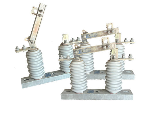
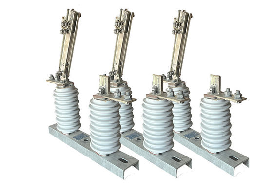
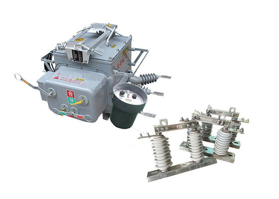
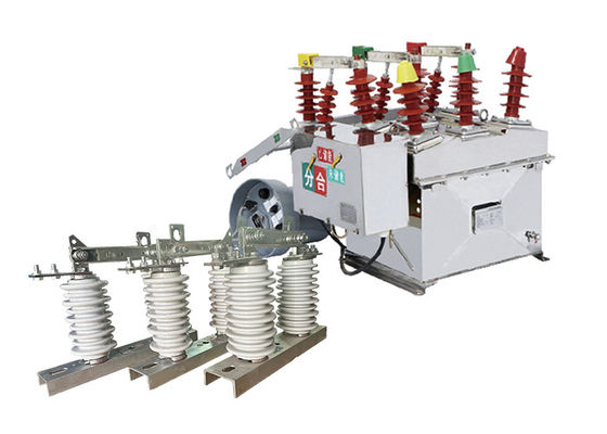
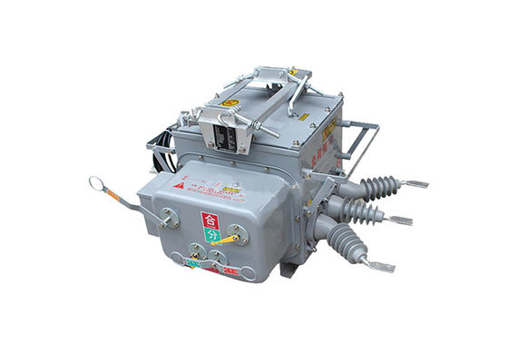
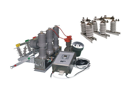
High voltage disconnect switch is an electrical device that is specifically designed for the purpose of isolating a particular section of an electrical network or system from the rest of the system. This is typically done to facilitate maintenance or repair work on the system. The switch is usually used in high voltage power transmission and distribution systems.
The switch is designed to open and close under normal operating conditions as well as under abnormal conditions, such as a fault or overcurrent. When the switch is open, it physically disconnects the section of the system from the rest of the network, preventing the flow of electricity to that section.
Structure:
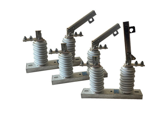
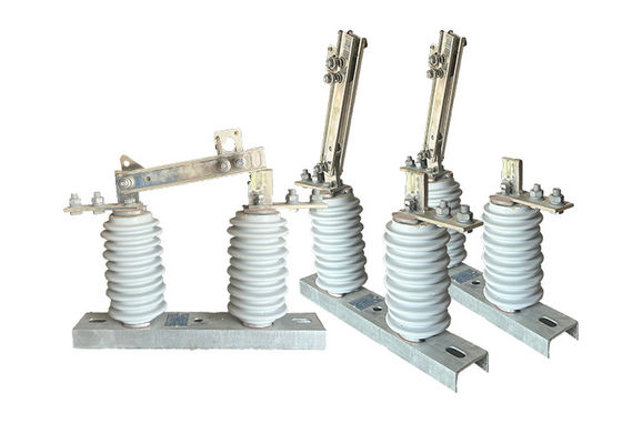
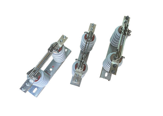
The product being described is composed of a base (plate), post insulator, conductive part, and interlock device. The knife is installed on the dynamic contact knife head through bolts and is separately connected with the static contact head. Each side is maintained in a good contact state by the pressure of the compression spring. The knife is a slot-shaped type, which increases the heat dissipation surface and reduces the temperature rise. This contributes to the mechanical strength of the knife and makes it dynamically thermally stable against short circuits.
The interlocking parts installed at the non-rotating end of the contact knife and the static locking hook on the static contact form the opening locking device. When the brake is closed, the device is self-locking, so the brake knife will not fall off due to its own weight or the action of electric power, which could cause the brake to open without cause.
This product is commonly used in power transmission and distribution systems and plays a crucial role in ensuring the proper functioning of the electrical grid. Proper safety procedures should be followed when working with these switches, and only qualified and trained personnel should be allowed to operate and maintain them.
Condition:
1.The maximum altitude for installation should not exceed 1000m.
2.The ambient air temperature should not exceed +40'C, and in general areas, it should not fall below -30'C. In Paramos areas, it should not fall below -40'C.
3.The wind pressure should not exceed 700Pa, corresponding to a wind speed of 34m/s.
4.The isolator should be able to withstand earthquakes of up to 8 degrees in intensity.
5.The isolator should be installed in a location where there is no frequent violent vibration.
6.For ordinary type isolators, they should be kept away from gas, smoke, chemical deposition, salt-spray fog, dust, and other explosive and corrosive materials that can seriously affect the isolator's insulation and conduction capability.
7.Pollution-proof type isolators are suitable for use in severely filthy conduction areas, but they should not be installed in areas with any explosive or fire-causing materials.
Technical Parameters:
Serial No. | Parameter | Unit | Data | |||||||||
1 | Rated Voltage | kV | 12 | |||||||||
2 | Rated Current | Model No. | (H)GW9-12(W)/630-20 | A | 630 | |||||||
(H)GW9-12(W)/1000-20 | 1000 | |||||||||||
(H)GW9-12(W)/1250-31.5 | 1250 | |||||||||||
3 | 4s Short-time withstanding current | Model No. | (H)GW9-12(W)/630-20 | kA | 50 | |||||||
(H)GW9-12(W)/1000-20 | 50 | |||||||||||
(H)GW9-12(W)/1250-31.5 | 80 | |||||||||||
4 | Rated Insulation Level | Lightning surge withstand voltage(peak) | Polar-to-Earth (Positive & Negative) |
kV | 75 | |||||||
Interfracture (Positive & Negative) |
85 | |||||||||||
Industrial frequency withstand voltage (1 min) (Effective value) |
Dry Test/Wet Test | Polar-to-Earth | 42(Dry) 34(Wet) |
|||||||||
Interfracture | 48(Dry) | |||||||||||
48(Dry) | ||||||||||||
48(Dry) 40(Wet) |
||||||||||||
5 | Main Circuit Resistance | μ Ω | 630 | |||||||||
1000 | ||||||||||||
1250 | ||||||||||||
6 | Mechanical Life Time | times | 50 | |||||||||
50 | ||||||||||||
80 | ||||||||||||