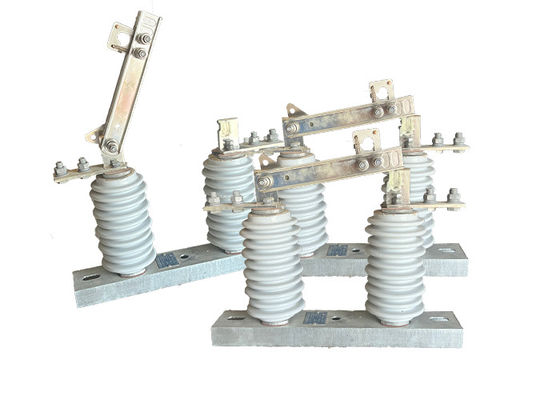
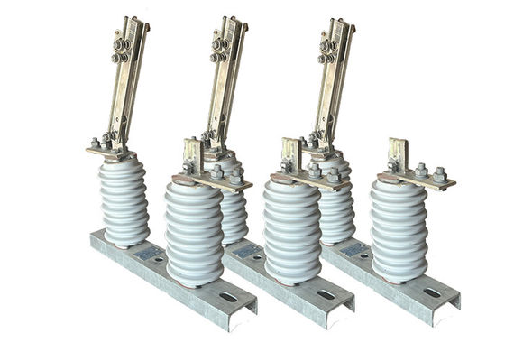
GW9-10/630A High Voltage DC Disconnect Switch Automatic Reset Installed On Overhead Power Lines For Protection
Product Description:
High voltage isolator switches are essential components in power transmission and distribution systems, as they allow for the isolation of specific sections of the network for maintenance or repair work. They can also be used to isolate sections of the network in the event of a fault or other abnormal condition.
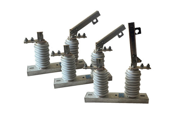
These switches are designed to handle high voltages and currents, and are typically constructed from durable and robust materials such as stainless steel, aluminum or copper. They are designed to withstand harsh environmental conditions, such as extreme temperatures, high winds, and heavy rainfall.
There are several types of high voltage isolator switches, including air-break switches, oil-immersed switches, and gas-insulated switches. Air-break switches are the most common type, and they wor k by using a set of contacts that physically separate when the switch is opened. Oil-immersed switches are typically used in high voltage applications and are filled with oil to prevent arcing when the switch is opened. Gas-insulated switches use sulfur hexafluoride gas to insulate the switch contacts, which allows for smaller and more compact switch designs.
High voltage isolator switches must be operated and maintained by qualified personnel who have received proper training. Safety procedures must be followed when working with these switches, including the use of appropriate personal protective equipment and following lockout/tagout procedures to prevent accidental energization of the equipment. Regular maintenance and testing of high voltage isolator switches is also important to ensure that they are functioning properly and are safe to use.
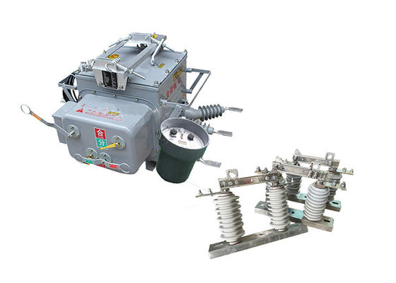
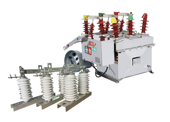
Relation with Outdoor Vacuum Circuit Breaker:
The relation between the outdoor vacuum circuit breaker and the outdoor high-voltage disconnect isolator lies in their complementary roles in the electrical system:
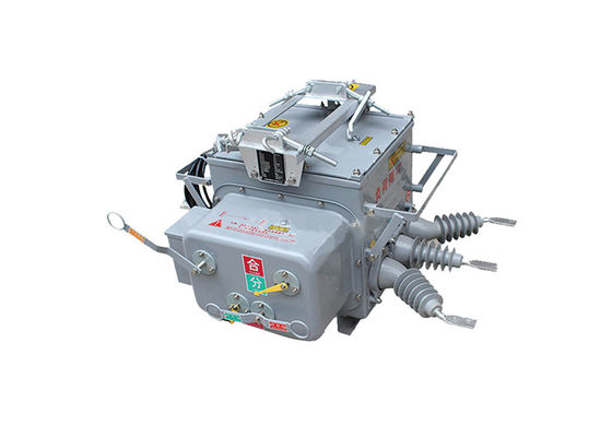
Circuit Interruption: The vacuum circuit breaker is responsible for interrupting the electrical circuit during normal operation or in the event of a fault. It acts as the primary means of breaking the current flow. In contrast, the disconnect isolator is used for isolating the circuit from the power source during maintenance or repair activities. It provides an additional layer of safety by physically opening the circuit.
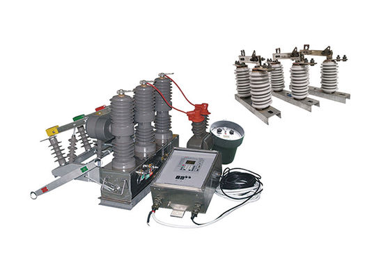
Coordination: In high-voltage power systems, the vacuum circuit breaker and the disconnect isolator are often coordinated to work together. The circuit breaker is responsible for detecting faults and tripping to interrupt the current flow, while the disconnect isolator is used to physically isolate the circuit and provide a visible indication of the disconnection.
Safety and Maintenance: The disconnect isolator plays a crucial role in ensuring the safety of maintenance personnel. Before any maintenance work can be performed on the electrical equipment, the disconnect isolator is operated to open the circuit and provide a visible air gap. This ensures that the equipment is de-energized and safe to work on. The vacuum circuit breaker, on the other hand, protects the system during normal operation and in the event of faults.
Operation:
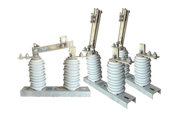
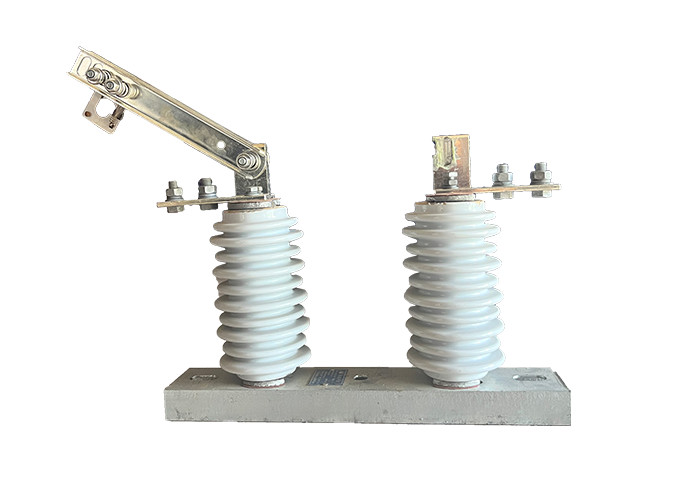
1.When the HV electrical isolator is in the closed position, the contacts of the isolator are in contact with each other, allowing current to flow through the circuit. Thet HV electrical isolator is closed by manually or remotely operating the isolator, depending on the type of the HV electrical isolator.
2.To isolate a section of the power system, the HV electrical isolator must be opened. This is typically done by manually or remotely operating the isolator to separate the contacts and interrupt the flow of current through the circuit.
3.Once the HV electrical isolator is opened, the section of the power system that is connected to the isolator is isolated from the rest of the system. This allows maintenance or repair work to be performed safely on the isolated circuit.
4. When the maintenance or repair work is complete, the HV electrical isolator can be closed to restore power to the isolated circuit. This is done by manually or remotely operating the isolator to connect the contacts and restore the flow of current through the circuit.
Advantage:
1.Simple structure: The isolation switch is designed with a straightforward structure, making it easy to understand and operate.
Low maintenance: Due to its design and construction, the isolation switch requires minimal maintenance, reducing the need for frequent inspections and repairs.
2.High breaking and closing linearity: The isolation switch has excellent breaking and closing linearity, ensuring smooth and reliable operation during switching operations.
3.High reliability: The switch is built to provide dependable performance, minimizing the risk of malfunctions or failures during operation.
4.Comparable to international standards: The GW9-12(W) series isolation switch meets or exceeds the level of similar products both domestically and internationally, ensuring its compatibility and competitiveness in the market.
Safety Tips:
1.Conduct routine testing and maintenance on the switch to ensure its proper functioning. This includes testing the switch's insulation resistance, verifying the operation of safety interlocks, and checking for any abnormal heating or vibrations.
2.Implement a lockout/tagout procedure before performing maintenance or repair work on the switch. This procedure involves locking and tagging the switch to prevent accidental energization while work is being carried out, providing an additional layer of safety.
3.Provide adequate training to personnel who will be operating or working on the switch. Training should cover proper handling, operation, and maintenance procedures, as well as the potential hazards associated with the switch.
4.Implement a comprehensive safety management system that includes regular safety audits, hazard assessments, and incident reporting. This proactive approach to safety helps identify and address potential risks before they result in accidents or injuries.
5.Ensure proper ventilation and cooling systems are in place for high voltage isolator switches located in enclosed or confined spaces. 6.Adequate ventilation helps dissipate heat and prevents the switch from overheating, which can lead to malfunctions or even fires.
Condition:
1.The altitude does not exceed 1000m
2.The ambient air temperature: Maximum+ 40'C ;Minimum:General Area -30'C, Paramos -40 C;
3.The wind pressure does not exceed 700Pa.(corresponding to 34m/s wind speed);
4.The earthquake intensity does not exceed 8 degrees;
5.The working situation is without frequent violent vibration;
6.The installation site of ordinary type isolator should be kept away form gas, smoke chemical deposition, salt-spray fog, dust
and other explosive and corrosive maters that affect seriously insulation and conduction capability of the isolator
7.Pollution-proof type isolator is applies to severe filthy conduction area, however, it shouldn't be any explosive matters and matters causing fire
Technical Parameters:
| Serial No. |
Parameter |
Unit |
Data |
| 1 |
Rated Voltage |
kV |
12 |
| 2 |
Rated Current |
Model No. |
(H)GW9-12(W)/630-20 |
A |
630 |
| (H)GW9-12(W)/1000-20 |
1000 |
| (H)GW9-12(W)/1250-31.5 |
1250 |
| 3 |
4s Short-time withstanding current |
Model No. |
(H)GW9-12(W)/630-20 |
kA |
50 |
| (H)GW9-12(W)/1000-20 |
50 |
| (H)GW9-12(W)/1250-31.5 |
80 |
| 4 |
Rated Insulation Level |
Lightning surge withstand voltage(peak) |
Polar-to-Earth
(Positive & Negative) |
kV |
75 |
Interfracture
(Positive & Negative) |
85 |
Industrial frequency withstand voltage
(1 min)
(Effective value) |
Dry Test/Wet Test |
Polar-to-Earth |
42(Dry)
34(Wet) |
| Interfracture |
48(Dry) |
| 48(Dry) |
48(Dry)
40(Wet) |
| 5 |
Main Circuit Resistance |
μ Ω |
630 |
| 1000 |
| 1250 |
| 6 |
Mechanical Life Time |
times |
50 |
| 50 |
| 80 |


 Your message must be between 20-3,000 characters!