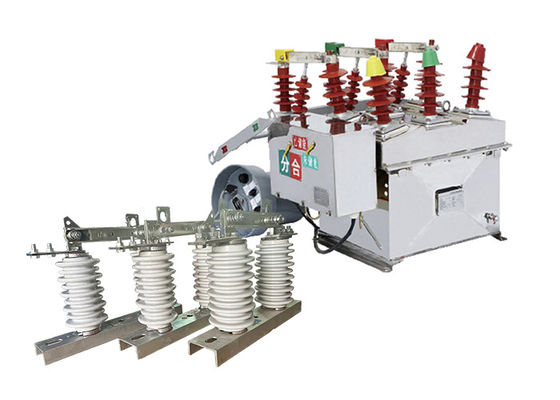
ZW8-12 High Voltage Vacuum Circuit Breaker For Protection Of Substation Using With GW9-10 Hookstick Operated Switch
Product Description:
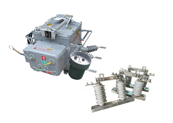
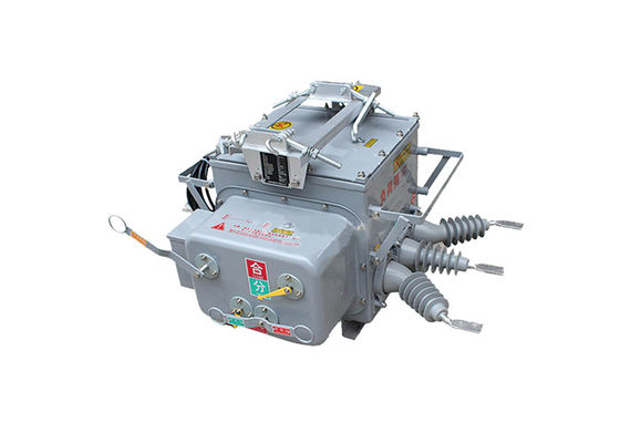
The ZW8-12 automatic vacuum circuit breaker is designed to comply with international standards and is manufactured using advanced technologies. It has a rated voltage of 12kV, a rated current of up to 630A, and a short-circuit breaking current of up to 20kA.
The circuit breaker is composed of several key components, including the vacuum interrupter, operating mechanism, and control system. The vacuum interrupter is the heart of the circuit breaker and is responsible for interrupting the electrical current. It is designed to operate in a vacuum, which helps to prevent arcing and ensures reliable operation.
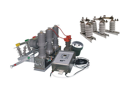
The operating mechanism is responsible for opening and closing the circuit breaker and can be operated manually or electrically. The control system monitors the circuit breaker and provides feedback to the operator, allowing them to monitor the status of the breaker and detect any faults.
The ZW8-12 pole mounted circuit breaker is designed to be highly reliable and requires minimal maintenance. It has a long service life and is capable of withstanding harsh outdoor environments, making it suitable for use in a wide range of applications.
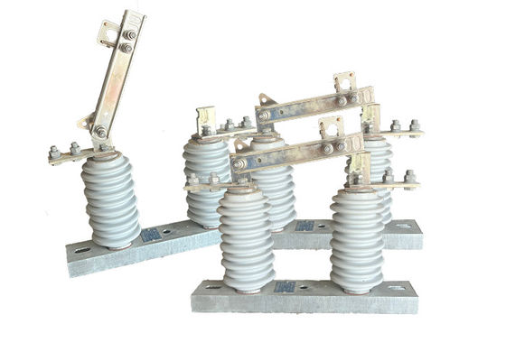
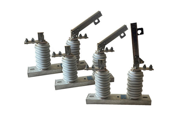
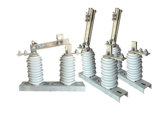
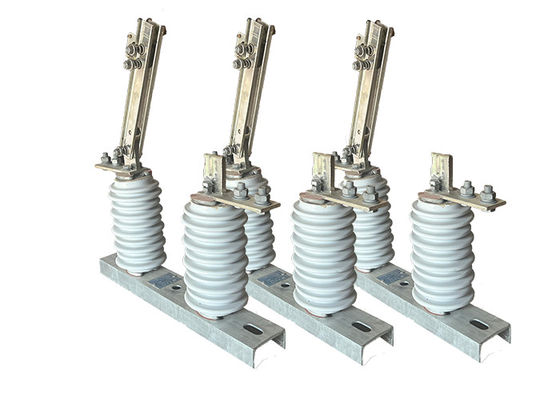
GW9-10 hookstick operated switch is a type of portable device used for isolating and grounding electrical distribution lines for maintenance, repair, or emergency purposes. It is a versatile tool that can be used in a variety of applications, including overhead distribution lines, substations, and industrial facilities.
The hookstick operated switch is designed to be operated by a single person, making it easy to use and maneuver. It consists of a telescoping fiberglass pole, which can be extended to reach the electrical equipment, and a set of interchangeable attachments, which allow the user to perform a variety of tasks, such as opening or closing switches and grounding lines.
The switch is designed to provide a visible break in the electrical circuit, which helps protect against accidental contact with energized equipment. It is also designed to withstand harsh environmental conditions, such as high winds, rain, and snow, making it suitable for use in outdoor environments.
Feature:
Microcomputer protection function
1.It has a three-stage current protection function: fast trip, time-limited fast trip, and overcurrent protection.
2.Flexible setting of fast and slow timing characteristics.
3.Users can set protection values and delays.
Reclosing function
1.Up to three reclosing operations can be set.
2.Users can freely choose the number of reclosing operations and different reclosing intervals.
3.It has functions of acceleration before reclosure, acceleration after reclosure, and sequential coordination selection.
Network reconstruction function
1.Includes undervoltage trip lockout, automatic reclosing, short-time no reclosing, continuous no reclosing, undervoltage reclosing, automatic reset, short-time activation of standby protection value, and continuous activation of standby protection value.
2.Distributed intelligent control can be realized according to the pre-set function during ring network operation.
3.When a network fault occurs, it automatically clears the fault, isolates the fault area, transfers power automatically, and restores power to the non-faulty area.
Measurement function
1.It records voltage, current, and other operating data, as well as event records.
FTU function
1.It can achieve four-remote functions of remote control, telemetry, remote signaling, and remote adjustment.
2.It includes remote control, various state remote monitoring, remote display of various measurement values and event records, and remote adjustment of various set values.
Communication interface and protocol
The controller is equipped with one data interface and standard remote communication protocol, supporting various communication methods such as fiber, wired, and wireless, serving as a remote terminal in the power distribution automation system.
Remote control function
It can be equipped with a wireless remote controller to achieve remote opening and closing operations at close range, with safe and reliable operation.
Backup battery
1.It can be equipped with a backup battery to maintain normal operation for 12 hours after AC loss.
Dual power switching protection function
1.It has dual power mutual control, with automatic delayed reclosure function on power-on and automatic delayed trip function on power-off.
2.The outgoing side has a function of not closing when there is electricity, and the two switch positions are interlocked.
Application:
1.Power Distribution Networks: The ZW8-12 circuit breaker can be used in medium-voltage distribution networks, such as substations, to protect transformers, feeders, and other electrical equipment from overloads and short circuits. It ensures reliable and safe operation of the distribution system.
2.Industrial Plants: Industries such as manufacturing plants, chemical facilities, and mining operations often utilize the ZW8-12 circuit breaker to protect critical equipment and machinery. It provides fault protection for motors, generators, switchgear, and other industrial electrical systems.
3.Industrial Power Systems: Industries with high-power requirements, such as manufacturing plants, mining operations, and large-scale infrastructure projects, often utilize the ZW8-12 circuit breaker to control and protect their high-voltage power systems. It helps in managing load currents and safeguarding the equipment from short-circuit fault currents.
4.Renewable Energy Systems: With the increasing adoption of renewable energy sources like wind and solar power, the ZW8-12 circuit breaker finds application in high-voltage switchgear systems associated with renewable energy generation. It aids in the efficient integration of renewable energy into the grid and ensures the safe operation of the power generation facilities.
Advantage:
1.CT23 Spring Energy-stored Operating Mechanism: The ZW8-12 circuit breaker is equipped with the CT23 type spring energy-stored operating mechanism. This mechanism utilizes stored mechanical energy in springs to facilitate the opening and closing of the circuit breaker contacts. It offers flexibility in operation, allowing for motorized or manual operation depending on the specific requirements of the application.
2.ZW8-12G Combined Breaker: The ZW8-12G model is a combined breaker that consists of the ZW8-12 circuit breaker and an isolator. This configuration enables it to function as a sectionalizer, providing the capability to isolate specific sections of a power distribution network for maintenance or fault identification purposes.
3.Three-Phase Assembled in a Tank Structure: The ZW8-12 circuit breaker features a three-phase assembled in a tank structure. This means that the breaker's components for each phase are enclosed within a common tank, providing a compact and space-saving design. The tank provides mechanical protection and enhances the overall robustness of the circuit breaker.
4.Vacuum Arc-Extinguishing Chamber and Insulation Material: Within the metal tank, the ZW8-12 circuit breaker incorporates a three-phase vacuum arc-extinguishing chamber. This chamber efficiently extinguishes electrical arcs that occur during circuit interruption. Additionally, the circuit breaker utilizes insulation materials, such as SMC (Sheet Molding Compound), to ensure insulation between phases and from phase to phase, enhancing its overall insulating strength.
5.Reliable Performance and High Insulating Strength: The ZW8-12 circuit breaker is known for its reliable performance and high insulating strength. It is designed and tested to meet stringent performance standards, ensuring dependable operation in various electrical conditions. The high insulating strength enhances the circuit breaker's ability to withstand and isolate electrical voltages, contributing to the safety and reliability of the electrical system
Technical Parameter:
ZW8-12
| Serial No. |
Parameter |
Unit |
Data |
| 1 |
Rated voltage |
kV |
12 |
| 2 |
Rated insulation level |
1min Industrial frequency withstanding voltage |
Dry Test |
42 |
| Wet Test |
34 |
| Lightning surge withstand voltage (Peak) |
75 |
| 3 |
Rated Current |
A |
630 |
| 4 |
Rated short-circuit breaking current |
kA |
20 |
| 5 |
Rated short-circuit breaking current times |
time |
30 |
| 6 |
Rated short-circuit switching current (peak) |
kA |
50 |
| 7 |
Rated peak withstanding current |
50 |
| 8 |
Rated short time withstand current |
20 |
| 9 |
Rated short-circuit duration |
S |
4 |
| 10 |
Breaking time
(Separate excitation decoupling) |
Max. operating voltage |
ms |
15-50 |
| Rated operating voltage |
30-60 |
| Min. operating voltage |
| 11 |
Closing time |
25-50 |
| 12 |
Full disconnection time |
≤100 |
| 13 |
Arc burning time |
≤20 |
| 14 |
Mechanical lifetime |
time |
10000 |
| 15 |
Closing function |
J |
70 |
| 16 |
Rated input power of energy storage motor |
W |
<250 |
| 17 |
Rated operating voltage/ rated auxiliary circuit voltage |
V |
DC220 |
| AC220 |
| 18 |
Energy storage time at rated voltage |
S |
<10 |
| 19 |
Overcurrent decoupler |
Rated Current |
A |
5 |
| Accuracy of decoupling current |
% |
±10 |
GW9-10
| Serial No. |
Parameter |
Unit |
Data |
| 1 |
Rated Voltage |
kV |
12 |
| 2 |
Rated Current |
Model No. |
(H)GW9-12(W)/630-20 |
A |
630 |
| (H)GW9-12(W)/1000-20 |
1000 |
| (H)GW9-12(W)/1250-31.5 |
1250 |
| 3 |
4s Short-time withstanding current |
Model No. |
(H)GW9-12(W)/630-20 |
kA |
50 |
| (H)GW9-12(W)/1000-20 |
50 |
| (H)GW9-12(W)/1250-31.5 |
80 |
| 4 |
Rated Insulation Level |
Lightning surge withstand voltage(peak) |
Polar-to-Earth
(Positive & Negative) |
kV |
75 |
Interfracture
(Positive & Negative) |
85 |
Industrial frequency withstand voltage
(1 min)
(Effective value) |
Dry Test/Wet Test |
Polar-to-Earth |
42(Dry)
34(Wet) |
| Interfracture |
48(Dry) |
| 48(Dry) |
48(Dry)
40(Wet) |
| 5 |
Main Circuit Resistance |
μ Ω |
630 |
| 1000 |
| 1250 |
| 6 |
Mechanical Life Time |
times |
50 |
| 50 |
| 80 |


 Your message must be between 20-3,000 characters!