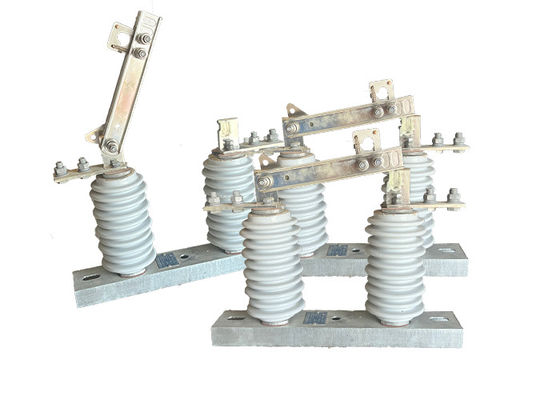
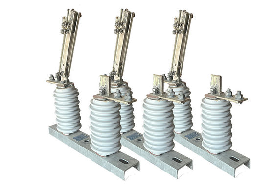
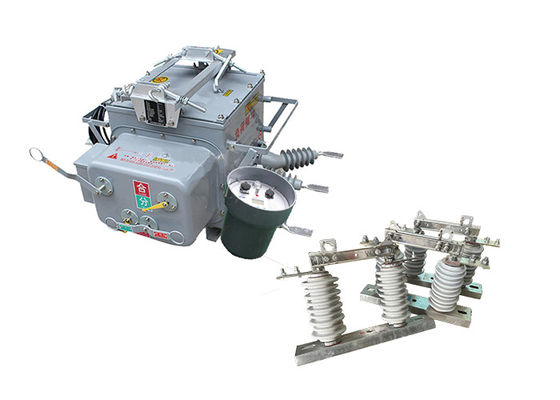
Porcelain High Voltage Electrical Isolator For Breaking Group Operated Disconnect Switches 700Pa Wind Pressure
Product Decription:
High voltage electrical isolators are commonly used in power transmission and distribution systems, where they provide a means of supporting and isolating high voltage power lines and equipment. They are designed to withstand high levels of voltage and electrical current, and are typically used in applications where reliability and safety are critical.
The construction of high voltage electrical isolator typically involves several key components, including a porcelain insulating body, metal end fittings, and a sealing compound. The insulating body is typically made of high-strength porcelain, which is molded into the desired shape and size and coated with a glaze to improve its electrical and mechanical properties. The metal end fittings are then attached to the insulating body, providing a means of attaching the isolator to the supporting structure or equipment.
High voltage electrical isolators are available in a range of shapes and sizes, and may be designed with specialized features to improve their performance and safety. These may include insulating barriers, arc chutes, and earth switches, among others.
Condition:
1.The altitude does not exceed 1000m
2.The ambient air temperature: Maximum+ 40'C ;Minimum:General Area -30'C, Paramos -40 C;
3.The wind pressure does not exceed 700Pa.(corresponding to 34m/s wind speed);
4.The earthquake intensity does not exceed 8 degrees;
5.The working situation is without frequent violent vibration;
6.The installation site of ordinary type isolator should be kept away form gas, smoke chemical deposition, salt-spray fog, dust
and other explosive and corrosive maters that affect seriously insulation and conduction capability of the isolator
7.Pollution-proof type isolator is applies to severe filthy conduction area, however, it shouldn't be any explosive matters and matters causing fire
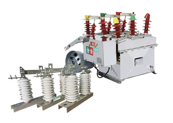
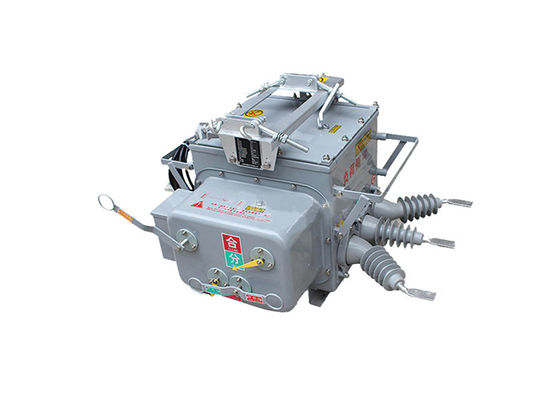
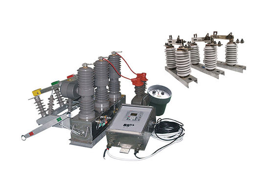
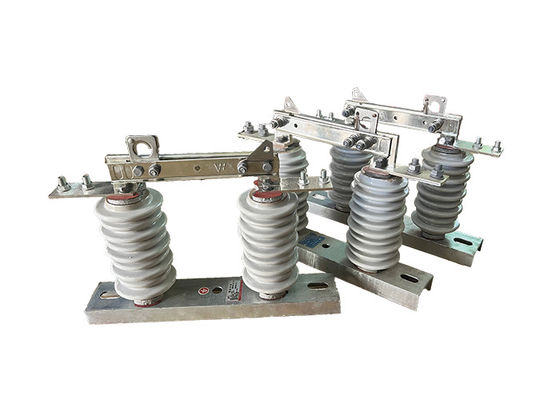
Structure:
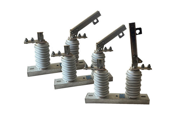
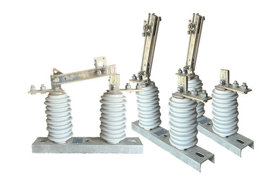
1.Porcelain Insulator Body: The insulator body is the main component of the isolator, and is typically made of high-strength porcelain. It is designed to provide electrical insulation between the conductor and supporting structure, and is molded into the desired shape and size.
2.Metal End Fittings: The metal end fittings are attached to the insulator body and provide a means of connecting the isolator to the conductor and supporting structure. They are typically made of galvanized steel or other corrosion-resistant material, and may be designed with special features such as clevises or ball-and-socket joints for easy installation.
3.Sealing Compound: A sealing compound is used to seal the joint between the insulator body and metal end fittings, preventing moisture and contaminants from entering the interior of the isolator.
4.Hardware: Hardware such as bolts, nuts, and washers are used to secure the metal end fittings to the insulator body and supporting structure.
Fitting Caps: Fitting caps are used to protect the metal end fittings from corrosion and damage, and may be made of plastic or other materials.
5.Additional Features: Depending on the specific application, porcelain high voltage electrical isolators may be designed with additional features such as insulating barriers, arc chutes, and earth switches to improve their performance and safety.
Operation:
1 Preparation: Before operating the switch, the circuit should be de-energized and properly grounded to prevent any electrical hazards. The switch should be inspected for any signs of damage or wear and tear.
2 Closing the switch: To close the switch, the operator manually or remotely moves the switch handle or control lever to the closed position. This connects the circuit to the power source, allowing current to flow through the circuit.
3 Opening the switch: To open the switch, the operator manually or remotely moves the switch handle or control lever to the open position. This disconnects the circuit from the power source, interrupting the flow of current.
4 Arc management: When the switch is opened, an electrical arc may occur between the contacts, which can be dangerous and cause damage to the switch. To manage the arc, the switch may be equipped with devices such as arc chutes or blowout coils.
5 Safety: Operators of high voltage disconnect switches must follow proper safety procedures to prevent electrical hazards. This may include wearing personal protective equipment, working in teams, and following lockout/tagout procedures.
Technical Parameters:
| Serial No. |
Parameter |
Unit |
Data |
| 1 |
Rated Voltage |
kV |
12 |
| 2 |
Rated Current |
Model No. |
(H)GW9-12(W)/630-20 |
A |
630 |
| (H)GW9-12(W)/1000-20 |
1000 |
| (H)GW9-12(W)/1250-31.5 |
1250 |
| 3 |
4s Short-time withstanding current |
Model No. |
(H)GW9-12(W)/630-20 |
kA |
50 |
| (H)GW9-12(W)/1000-20 |
50 |
| (H)GW9-12(W)/1250-31.5 |
80 |
| 4 |
Rated Insulation Level |
Lightning surge withstand voltage(peak) |
Polar-to-Earth
(Positive & Negative) |
kV |
75 |
Interfracture
(Positive & Negative) |
85 |
Industrial frequency withstand voltage
(1 min)
(Effective value) |
Dry Test/Wet Test |
Polar-to-Earth |
42(Dry)
34(Wet) |
| Interfracture |
48(Dry) |
| 48(Dry) |
48(Dry)
40(Wet) |
| 5 |
Main Circuit Resistance |
μ Ω |
630 |
| 1000 |
| 1250 |
| 6 |
Mechanical Life Time |
times |
50 |
| 50 |
80
|


 Your message must be between 20-3,000 characters!